1°/ Introduction
When a µC is connected to a device (like sensors) through GPIOs, to acquire data, there are several ways to communicate data.
The first one is "direct": the µC reads directly the state of some digital pins of the device. So, there is no need of a protocol of communication because the retrieved information is binary. This solution is used to test the state of a switch, if a ligth sensor reaches a given threshold of luminosity, ...
The second one is quite similar but it uses an analog pinn which receive a variable voltage from the device. The µC converts the voltage into an integer value (using an ADC circuit). Again, no need of protocol. This is very often used by "cheap" sensors measuring a variable phenomena like temperature, pressure, ... Generally, the range of measure is quite narrow and the accuracy of result is weak.
The last one is to read/write sequences of bits, that represent the data. In that case, both sides must agree on the speed of transmission and how bits are transmitted, hence the use a communication protocols.
In the electronic world, there are 3 "historical" protocols that are widely used for µC devices :
- serial protocol
- I2C
- SPI
2°/ serial protocol
This protocol uses a pair of pins named RX (receiving) and TX (transmitting), used by both communicating sides. In order to work, the TX pin of one part must be linked to the RX pin of the other, an reversly, as shown on the figure below.
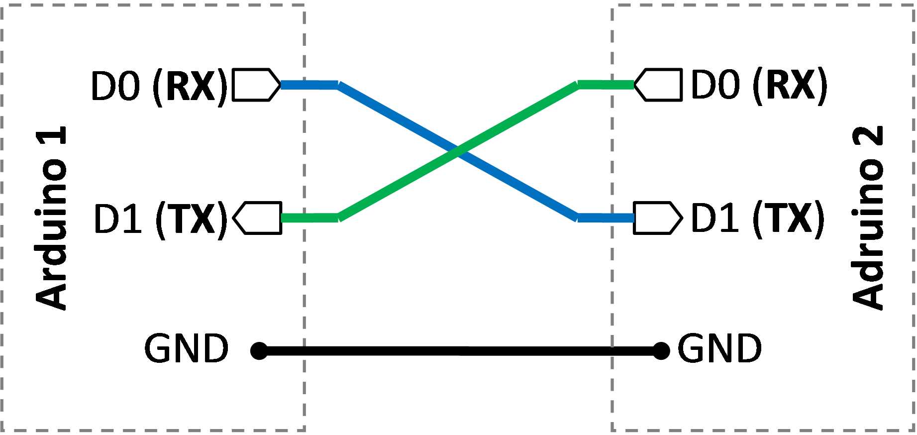
Technically, if one side does not need to send, only one pin on each side is needed. Nevertheless, there is no wire to transmit a clock signal to synchronize both parts.This is why they must firstly agree on the same speed to transmit bits, expressed in bauds (roughly bits per seconds). Otherwise, they won't be able to understand each other.
Some µC (as the esp8266/32) have one or several internal circuits called UART, able to manage serial protocol. They are called hardware UART/Serial because they are within the µC. Depeding on the µC, these UART are linked to dedicated GPIOs, or can be routed to any one. For example, esp32 integrates 3 UARTs, which use by default pairs RX/TX on pins [3,1], [9,10] et [16,17], but we can assign the pairs to any other GPIO.
In arduino, UART are already available as pre-existing object, generally called Serial, Serial1, Serial2, ... respectively associated to UART 0, 1, 2, ... of the µC.
A serial link is widely used by sensors that are sending variable or big amount of data, generally as line of text. This is the case of GPS devices.
Example of a GPS device plugged on pins 27, 28 of an esp32, but using UART 2 (thus Serial2) to read from the GPS
void setup() {
  Serial.begin(115200);
  Serial2.begin(9600, SERIAL_8N1, 27, 28);
}

void loop() {
  while (Serial2.available()) {
    Serial.print(char(Serial2.read()));
  }
}
CAUTION: UART 0 (associated to Serial) is generally used in sketch to communicate with a computer. By default, UART 0 is linked to pins 3, 0, which are themselves linked to a chipset that is able to convert serial protocol to/from USB protocol. This is why a computer can receive and send something the/from the µC. Unfortunately, if UART 0 is used that way, it prevents to use it to communicate with an other device. In consequence, either we can debug using Serial, or we use it to communicate with a device. But never both at the same time.
The main problem of the serial protocol is that it does not allow to link several device using the same wires. A new pair of pins must be used for each device. It is a big constraint since most of µC have only between 1 to 3 UARTs. If there are no available UART, they must be emulated by software. It is the role of the library SoftwareSerial. Nevertheless, this emulation loads the µC so much that it is not usable to drive more than one or two devices.
Example with SoftwareSerial on pins D5, D6 of esp8266 :
#include <SoftwareSerial.h>
#define baudrate 9600

SoftwareSerial mySerial(D5, D6); // RX, TX

void setup() {
  Serial.begin(115200);
  mySerial.begin(baudrate);
}
The second problem of serial protocol is the communicating speed. In theory, it can reach 1Megabauds, but in practice, it is rarely above 115Kbauds. It is even less with software emulation, which is generally used at 9600 bauds. Moreover, some devices are stucked on 9600 bauds.
2°/ I2C
This protocol uses a simple bus, shared by the devices and the µC, as shown on the illustration below. It allows to chain a lot of devices, BUT under some conditions
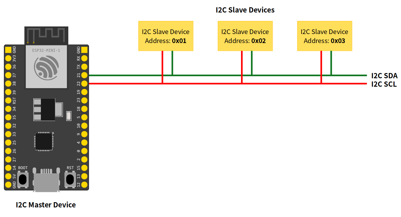
This protocol is based on a notion of master and slave, with communication between master and slaves, but never between slaves. The constraint are :
- each slave must be identified by a different address on the bus, which is a simple byte value (bewteen 0 - 255)
- all must be connected to a pair of pins called SDA and SCL. SDA transmits bits and SCL a clock signal to synchronize all participants.
As for UARTs, most of µC are able to manage I2C "by hardware", using an internal circuit linked to dedicated pins, e.g. 21 & 22 on the esp32. Depending on the µC, these pins can be override and other used. On the esp32/8266, we can use nearly every pair of pins.
It must be noticed that this bus is bidirectional so slaves can send AND receive. Furthermore, the master can send to a particular lave or to all (=broadcast)
The default speed is 100Kbits/s, but it may be raise most of the times up to > 1Mbits/s if devices allow it.
The main limitation of I2C is the use of addresses. Indeed, devices receive a fixed address from their manufacturers. Sometimes device have two possibles addresses but never more. For example, the BME280 sensor (temperature, humidity, pressure) may use address 0x76 or 0x77. Thus, it is not possible to put more than two BME280 on the same I2C bus. Moreover, if another device also uses these addresses, it will not be usable on the same bus. Nevertheless, it is still possible on some µC to create several I2C buses, or a chipset that is able to multiplex several buses.
In arduion, we use the Wire library to use I2C. As for the serial protocol, the begin() function is used to initialize the protocol and to specify what pins are used for SDA & SCL, and the clock frequency. API and example for the esp32 can be found here : https://espressif-docs.readthedocs-hosted.com/projects/arduino-esp32/en/latest/api/i2c.html
For practical examples, notably on issues about using I2C with other libraries, or addresses conflicts: https://randomnerdtutorials.com/esp32-i2c-communication-arduino-ide/
3°/ SPI
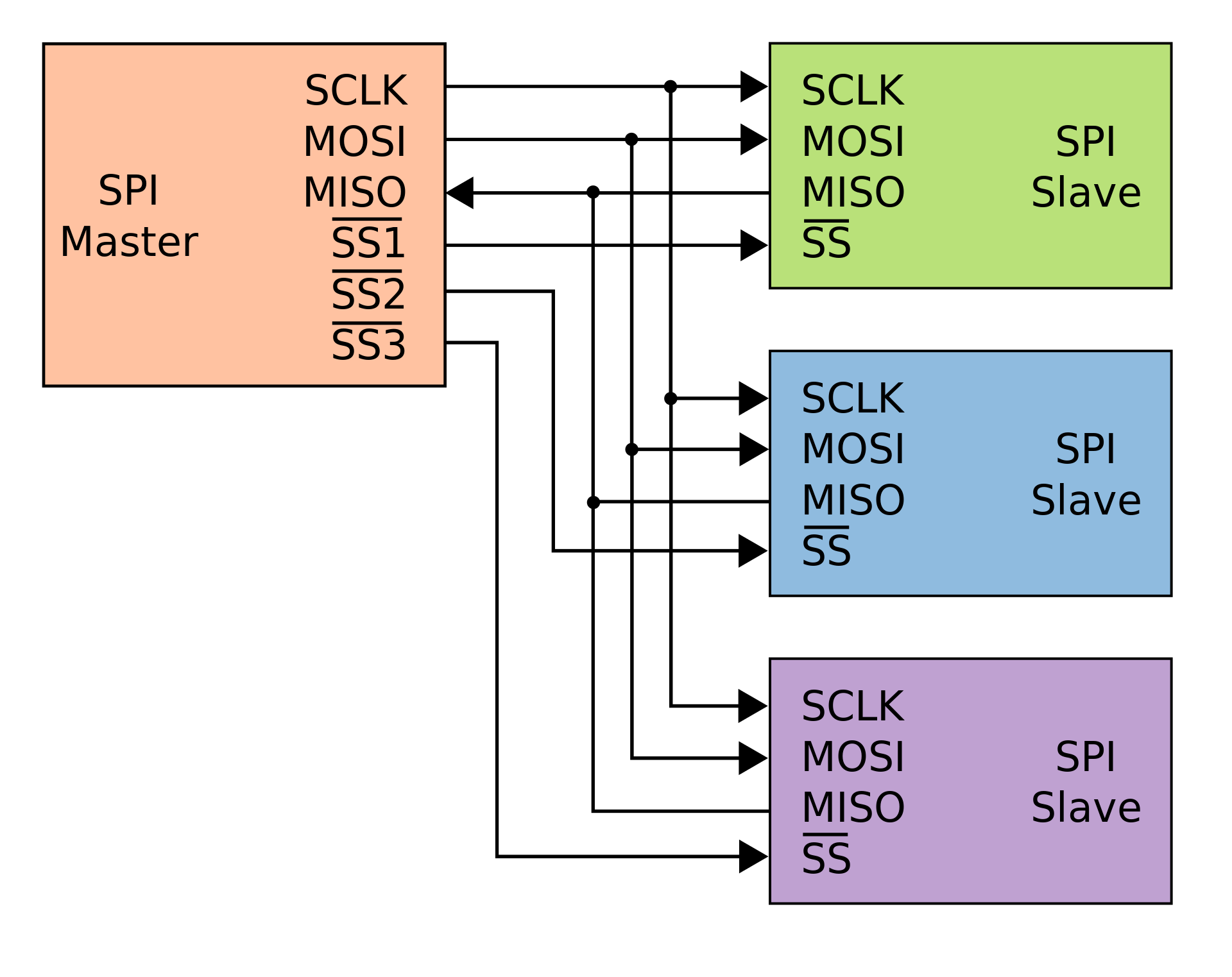
SPI protocol is relatively similar to I2C, except that there are no addresses to specify what device must communicate, and two wires are used to communicate data: MISO = from slave to master, MOSI = from master to slave. Not using address implies that master must have a way to select the device it wants to communicate with This is done through dedicated wires and pins, called chip-select pins (CS or SS), one for each device, as shown on the figure below. If the master has 3 slaves, there must be 3 wires for MOSI, MISO and clock, plus 3 additional wires to select the salves.
NB: the bar above SS pins means that the polarity of the digital signal is reversed. If a device receives 0 on SS, it is selected to communicate. If 1, it does nothing.
The SPI bus consumes much more GPIOs than I2C, which can be problematic on small µC, with few GPIOs.
As for I2C, µC have generally dedicated hardware to manage SPI and dedicated pins, but only for MISO, MOSI and clock. In some µC, these pins can be reassigned.
In arduino, SPI protocol is rarely used directly. Generally, we install libraries dedicated to the devices using SPI. These libraries provide functions that mask the use of SPI.
It can be noticed that some devices are able to work with both SPI & I2C., for example the BME280 sensor.