1°/ program structure
- an arduino program is called a sketch.
- a sketch contains at least 2 functions :
- void setup() : used to initialize global variables, serial communications, sensors, wifi connection, ... It is executed only once, just after the boot sequence.
- void loop() : the execution entry point. As soon as it terminates, it starts again. So loop() is called endlessly, until the micro-controller crashes, resets, shutdown, ...
- obviously, the developer can create other functions.
- As in a C program, variables can be global or local to functions.
- Generally, global variables are declared at the top of the sketch, after the #include and #define.
2°/ reading/writing on GPIO pins
- a micro-controller (µC) has several GPIO (General Purpose Input/Output) pins, that can be connected to other electronic parts/devices.
- The number of GPIOs depends on the type of µC.
- Moreover, not all these pins are usable on a development board.
- For example, an esp8266 has 18 GPIOs, but on most dev. boards, GPIO from 6 to 11 are not usable. But there may be other pins that are not usable on some board of a specific builder.
- This is why boards are not totally exchangeable even if they host the same µC:
- available GPIOs may be not the same,
- the physical organisation of the pins on the board may greatly vary.
- According to their name, these pins can be used as an input or an output. But there are some exceptions !
- These pins can be digital or analog:
- digital : allows to read/write a digital signal, i.e. a 2-states HIGH/LOW signal. HIGH corresponds to the high level voltage (3.3V on esp8266, 5V on ATmega328), and LOW to 0V.
- analog : allows to read/write a signal that can vary between LOW and HIGH voltages. This variation is not continuous, but discretized over 1023/4096/... steps (depends on the µC).
- For "electronic" reasons, the capacity to read or write on an analog pin is physically fixed: it reads or writes, but not both mode.
- For a digital pin, we can set the mode via a function call.
- esp8266 boards generally provide a single input analog pin and no output analog pin. esp32 boards generally provide 3 or 4 analog inputs, and 2 analog outputs.
- In order to simplify the µC programming, sketches do not use the real pin number on the µC : we use surnames, which are normally the same for all board builders.
- These surnames vary depending on the µC. On the esp8266, they are A0, D0, D1, D2, ..., but on esp32, they are only number : 0,1, 2, ...
- For example, if you read pin D3 of an esp8266 board, it normally corresponds to the GPIO 0. If you read pin 12 of an esp32 board, it normally corresponds to the GPIO 12.
- To setup the digital pin mode, we call pinMode().
- If the pin never changes of mode during the sketch execution, we set the mode in the setup() function. But, if its role changes (NB: pretty rare), we can also use pinMode() in loop().
- Exemple (for esp8266) :
// example with esp8266 pins
void setup() {
  pinMode(D3, OUTPUT);
  pinMode(D2, INPUT);
  ...
}
- reading/writing on the pin depends on its type.
- Exemple (for esp8266) :
int val = analogRead(A0); // read a value from 0 to 1023, which correspond to 0V and 3.3V
byte b = digitalRead(D2);
...
digitalWrite(D3,HIGH); // on an esp8266, D3 now outputs 3.3V
digitalWrite(D3,LOW); // on an esp8266, D3 now outputs 0V
3°/ Serial communication with a PC
- Most of dev. boards host a chipset that allows to send a program to the µC through an USB cable.
- In fact, this chipset allows to establish a serial connection between a PC and the µC. So it can be used to send or receive any data to/from the µC.
- Most often, the connection is used to debug our programs by printing messages, that will be send through the serial connection, and thus that can be displayed on the PC.
- Exemple :
...
void setup() {
  Serial.begin(115200); // initialize serial connection at 115200 bauds
  Serial.println("hello");
  ...
}
- The speed of the connection must be chosen according to the capacities of the µC.
- For example, ATmega328 (on arduino boards) allows only 9600 bauds.
4°/ Interrupts
- Some µC are able to monitor the state of some GPIOs (CAUTION : only digital ones) and check if there are some changes.
- In that case, they can interrupt what they were doing and call a function (i.e. a callback function) that must process the change event.
- It is particularly useful to react to push on a button/switch/... because it avoids to regularly check the state of this element within the loop() function.
Exemple : react to a change on pin D3 of an esp8266 board.
volatile byte state;
...
void ICACHE_RAM_ATTR mycallback() {
  state = digitalRead(D3);
  ...
}
...
void setup() {
  ...
  attachInterrupt(digitalPinToInterrupt(D3), mycallback, CHANGE);
  ...
}Remarks:
- There are 2 constraints to write a callback :
- we must enforce the compiler to create a code where the callback function will be placed in RAM memory (and not in the cache) : use ICACHE_RAM_ATTR macro in the function header.
- global variables manipulated by the callback must also stay in RAM memory (and not in cache/registers) : use volatile keyword.
- The name of the callback function is free, provided you use the same name in attachInterrupt().
- CHANGE will detect a state change, i.e. going from LOW to HIGH or the opposite. RISING will detect only a change from LOW to HIGH, and FALLING will detect a change from HIGH to LOW.
- digitalPinToInterrupt() is used to "convert" the name of a GPIO into a number that is proper to the µC interrupts numbering (NB: this numbering imay be different from the associated GPIO number).
5°/ Pulse Width Modulation (PWM)
- PWM is a principle that uses a digital pin to emit a signal that is constituted of pulses more or less large.
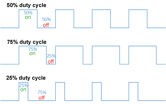
- During a pulse, the signal level is high, and low the rest of the time.
- The ratio between the time passed at low and high level is called the duty cycle.
- Generally, it is expressed as a percentage, as we can see on the picture below.
- The other parameter of PWM is the "frequency" of the signal: considering the time taken by a single low level+high level, we obtain the period of the signal and thus the frequency.
- For exemple, if the PWM frequency is 100Hz, the period is 10ms. Then, if the duty cycle is :
- 10% : the signal is low during 9ms then high during 1ms.
- 50% : the signal is low during 5ms, then high during 5ms.
- 80% : the signal is low during 2ms, then high during 8ms.
- This principle is used to power up a device like a led, a motor, ... so that a human sees a continuous phenomena while it is physically discretized.
- It leads to regulate the brightness of a led or the rotation speed of a motor.
- Depending on the µC, there are more or less digital pins that are able to produce a PWM signal (NB: nearly all on an esp8266)
- CAUTION : 3 functions are used to set up PWM and their names are all starting with analog.... It is just because PWM "simulate" an kind of analog signal, but it is really done with digital pins. In fact, analog pins are never able to produce such a signal.
- analogWriteRange(range) : used to set the range of the duty cycle. It defines the number of steps we can further use to setup the duty cycle value (without counting duty cycle at 0%). For exemple, if the range is 2, possible duty cycles are 0%, 50% and 100%. If the range is 100, we can set the duty cycle close to 1%.
- analogWriteFreq(freq) : used to set the frequency of the signal. Possible values depend on the µC and the duty cycle range (i.e. the lower the range, the higher frequency we can reach). For example, on an esp8266, frequency goes from 100Hz to about 40KHz.
- analogWrite(pin, dc) : starts the PWM on the pin given as a parameter, with dc as a value of duty cycle within the range specified before. It corresponds to a duty cycle in percent = 100*dc/range. For example, if range = 4 and dc = 1, the duty cycle is 100*1/4 = 25%
Example :
analogWriteRange(100); // allows to set duty cycle to 0, 1, 2, ..., 99, 100%
analogWriteFreq(10000); // 10KHz
analogWrite(D3,10); // duty cycle of 10/range = 10/100 = 10%
6°/ Interlude about power consumption
- Using wifi (and/or bluetooth) on a µC is the main source of power consumption.
- For example, an ESP32 sending over wifi draws up to 250mA from the power supply, and about 100mA while receiving
- If Wifi is active but not communicating, it is around 80-100mA.
- This is huge and constitue a real problem if the µC is powered by batteries. For example, a 1000mAh battery is able to supply 100mA for 10 hours.
- So it is important to lower the power consumption.
- The first strategy implemented in esp32/8266 is to regularly put the wifi in an inactive state, which is called the modem sleep mode. This is the default operation mode, so there is no instruction to execute to go into this mode.
- The duration of the sleep is determined by the interval between 2 DTIM emitted by the Wifi access point. It is generally between 100 and 1000ms.
- In this mode, the power consumption falls down to 20mA, except when the wifi is active and communicating, for which it is still 250mA. Thus, if the µC does not communicate continuously, it is an interesting mode.
- The drawback of this mode is that the wifi is not always active so there is a bigger latency to receive messages.
- When the µC communicates rarely, it is possible to save much more power, by entering light-sleep mode, deep-sleep mode or even hibernation.
- The difference between these 3 modes is that there are more or less parts of the µC that are inactive and the awakening process is different :
- light-sleep : the CPU is paused and awakes after a predetermined amount of time. The state of the processor is stored in the RAM, which is still powered. So application data are not lost too during the sleep. The consumption falls to 1mA but the µC is unable to receive messages during the sleep, so if someone sends something, it will be lost.
- deep-sleep : the CPU and the RAM is stopped and only RTC (realtime clock) circuits are active. So all application data are lost (NB : it is still possible to save few values in RTC RAM that is still powered). It awakes after a predetermined amount of time or with an external signal on a GPIO. When awakening, it boots once again. While in deep-sleep, it draws about 10µA
- hibernation : all is off and it can be awakened only by an eternal signal. In this mode, it draws about 2µA.
- Caution : all the current consumptions are given only for the µC. The real consumption is higher because of all chipsets that are used on the PCB around the µC (voltage regulator, usb-serial converter, ...). For example, it is quite common to obtain a real consumption around 50µA in deep-sleep.
- Apart these modes, it is also possible the switch off wifi when it is not needed : WiFi.mode(WIFI_OFF)
- It is also possible to set wifi always active, in case of small latency is needed : WiFi.setSleepMode(WIFI_NONE_SLEEP)
7°/ Deep sleep
- As said above, the deep sleep mode is usefull to save the battery.
- Generally, the deep sleep mode lasts for a given duration, or when an external signal is received.
- the first solution is used when the µC must do something regularely, and the second when an event like a push on a button or a sufficient light must trigger the µC awakening.
- In both cases, the drawback is that the µC reboots after resuming form deep sleep, so the content of the RAM is lost. Nevertheless, the RTC RAM is able to store few bytes : 512 on esp8266 and 8192 on esp32.
- Another drawback is that going into/out of deep sleep, accessing RTC RAM is quite different between esp8266 and esp32.
7.1°/ on esp8266
- In order to put the µC into deep sleep, we only need to call the funciton ESP.deepSleep(long time)
- time is the duration for which the µC sleeps. If = 0, it lasts until an external signal is received.
- In order to wake the µC from deep sleep, its RST pin must be set to ground (0V). There are 2 solutions to do such a thing, depending on the awakening mode:
- after a given time : the GPIO 16 (normally pin D0 an esp8266 dev. boards) must be connected (through a simple wire) to the RST pin. When timer ends, GPIO 16 will automatically emit a low signal (=0V)
- with external signal : the RST pin is directly fed with a signal that is high by default and goes low when a given event occurs. It can be for example a push button linked tu a pull-up resistor.
- In order to read/write values in the RTC RAM : ESP.rtcUserMemoryRead() and ESP.rtcUserMemoryWrite()
Exemple (for esp8266):
uint32_t bootcount;
void setup() {
  Serial.begin(115200);
  ...
  ESP.rtcUserMemoryRead(0, &bootcount, sizeof(bootcount));
  Serial.println(bootcount);
  ...
  bootcount++;
  ESP.rtcUserMemoryWrite(0, &bootcount, sizeof(bootcount));
  ...
}
void loop() {
  ...
  ESP.deepSleep(5000000); // sleep 5s, (=5000000µs)
}
7.2°/ on esp32
- Deep sleep is easier to setup compared to esp8266, and more versatile:
- no pin needed when a timer is used to wake-up,
- several pins (0, 2, 4, 12-15, 25-27, 32-39), can be used to provide an external signal that wakes up the µC, choosing high or low level as triggering value,
- there can be a mix between timer and external wakeup, and it is possible to know which one just occured,
- manipulating RTC RAM is done through RTC_DATA_ATTR macro before variables.
Example (for esp32):
RTC_DATA_ATTR int bootCount = 0;

// print the reason by which ESP32 has been awaken from sleep
void print_wakeup_reason(){
  esp_sleep_wakeup_cause_t wakeup_reason;
  wakeup_reason = esp_sleep_get_wakeup_cause();
  switch(wakeup_reason)  {
    case ESP_SLEEP_WAKEUP_EXT0 : Serial.println("Wakeup caused by external signal using RTC_IO"); break;
    case ESP_SLEEP_WAKEUP_EXT1 : Serial.println("Wakeup caused by external signal using RTC_CNTL"); break;
    case ESP_SLEEP_WAKEUP_TIMER : Serial.println("Wakeup caused by timer"); break;
    case ESP_SLEEP_WAKEUP_TOUCHPAD : Serial.println("Wakeup caused by touchpad"); break;
    case ESP_SLEEP_WAKEUP_ULP : Serial.println("Wakeup caused by ULP program"); break;
    default : Serial.printf("Wakeup was not caused by deep sleep: %d\n",wakeup_reason); break;
  }
}

void setup() {
  Serial.begin(115200);
  ++bootCount;
  Serial.println(bootCount);
  print_wakeup_reason();
  // configure pin 33 as external wakeup source
  esp_sleep_enable_ext0_wakeup(GPIO_NUM_33,1); //1 = High, 0 = Low
  // configure deep sleep timer
  esp_sleep_enable_timer_wakeup(5000000); // time in µ-seconds
}

void loop() {
  delay(1000);
  Serial.println("Going to sleep now");
  esp_deep_sleep_start();
  Serial.println("This will never be printed");
}